Upgrade Your BMW Interior: X3 G01 & X4 G02 Ambient Lighting Installation Tutorial
Step-by-step ambient lighting installation for BMW X3 (G01) & X4 (G02) — wiring, soldering, controller setup, CD-panel controls and troubleshooting.
Tools & Parts
- 4P power cord & large knob adapter
- Ambient LED lamp strips ×4 (one per door)
- Central controller / screen & dial
- Soldering iron, solder, cutters
- Heat-shrink tubing, zip ties, insulating tape
- Programming cable & laptop (for coding)
Step-by-step Installation
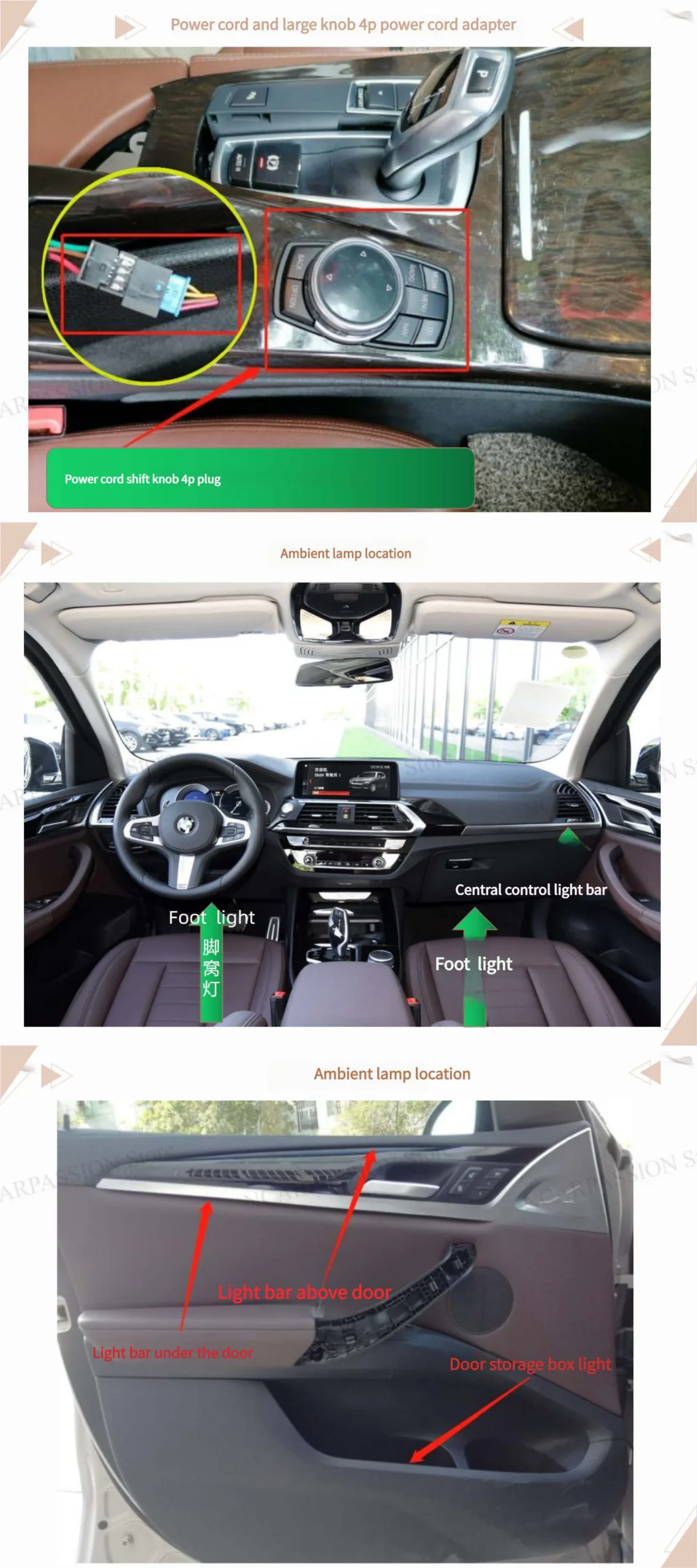
- Find power cord & control knob (4P power cord adapter).
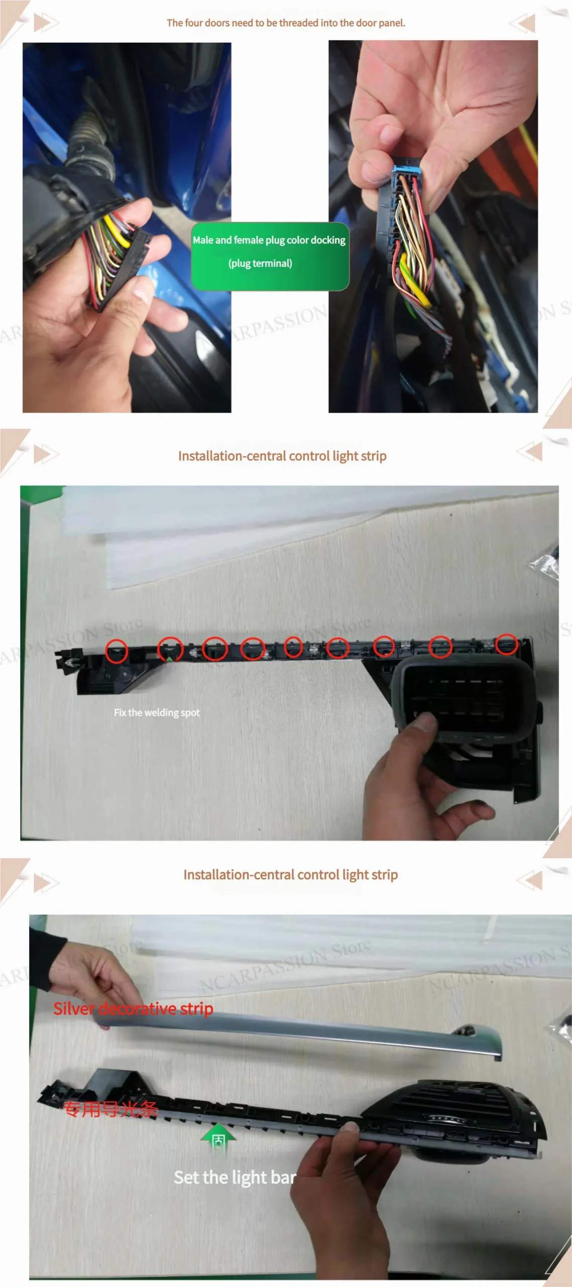
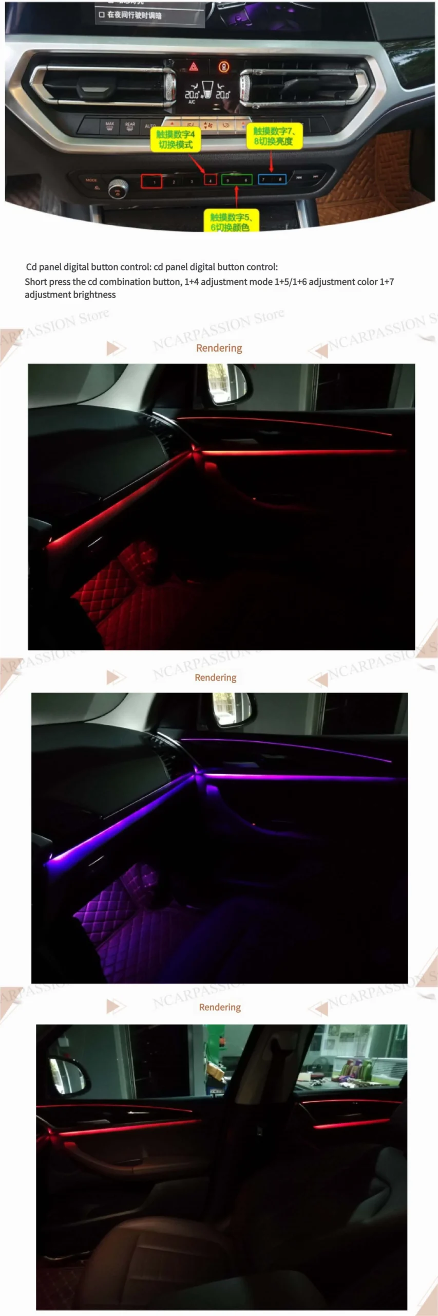
Locate the 4P power adapter position and the control knob mounting point. Confirm the ambient lamp locations on each door before beginning. - Thread wiring through door panels.
For all four doors, feed the lamp wires into the door panel through existing grommets or wire channels. Leave enough slack to allow door movement without straining the wires. - Male & female plug color docking (plug terminal).
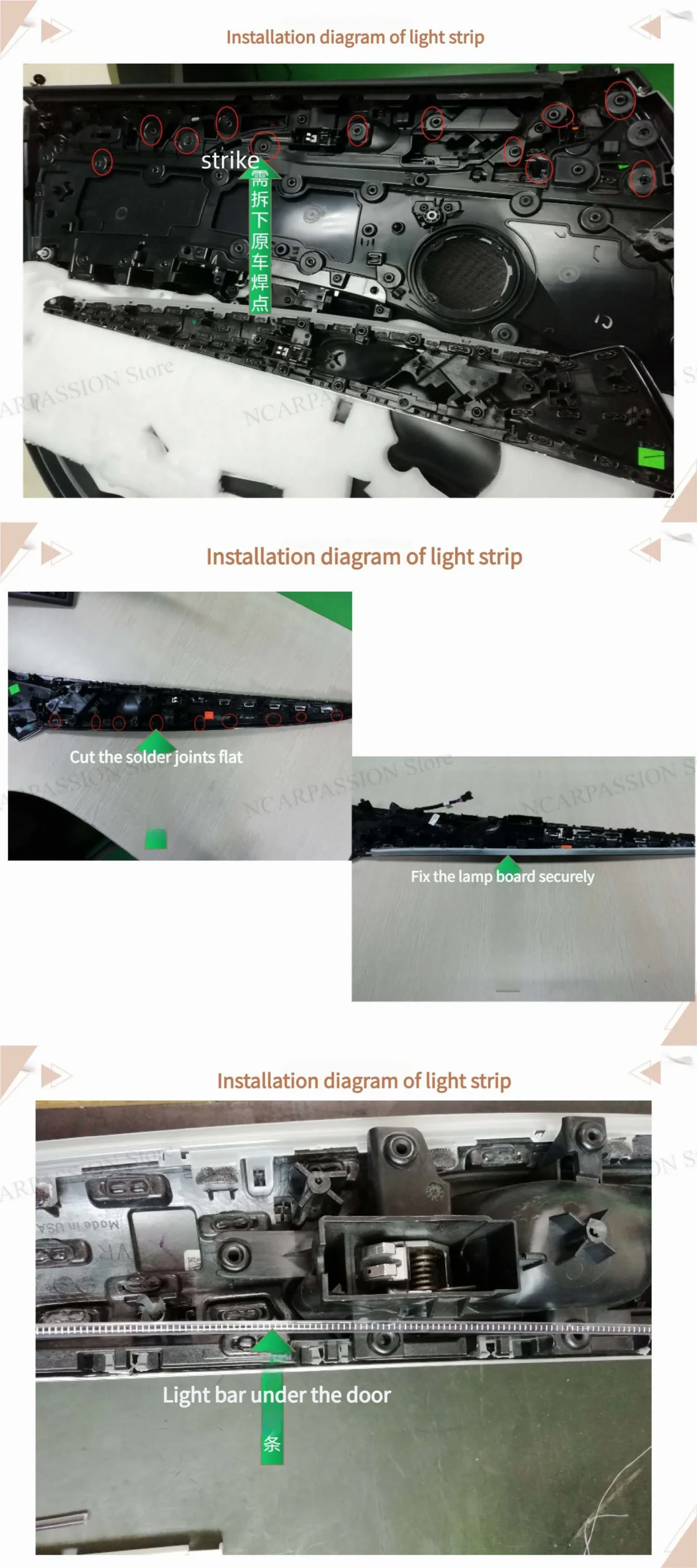
Match male and female connectors by color or label. Ensure connectors click into place and perform a gentle pull test so they won’t loosen over time. - Install central control light strip & prepare solder joints.
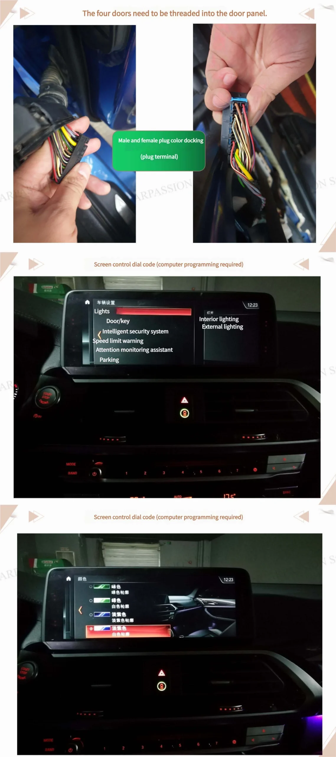
Mount the central control light strip where planned. Cut solder joints flat and clean; file or trim any raised solder points. Secure the lamp board so nothing will be pinched when reassembling the panel. - Set and mount the door light bars.
Follow the installation diagram to place light bars under the door trim. Make sure the strip sits flat and cannot be compressed by the trim or panel. - Repeat for all four doors & verify connectors.
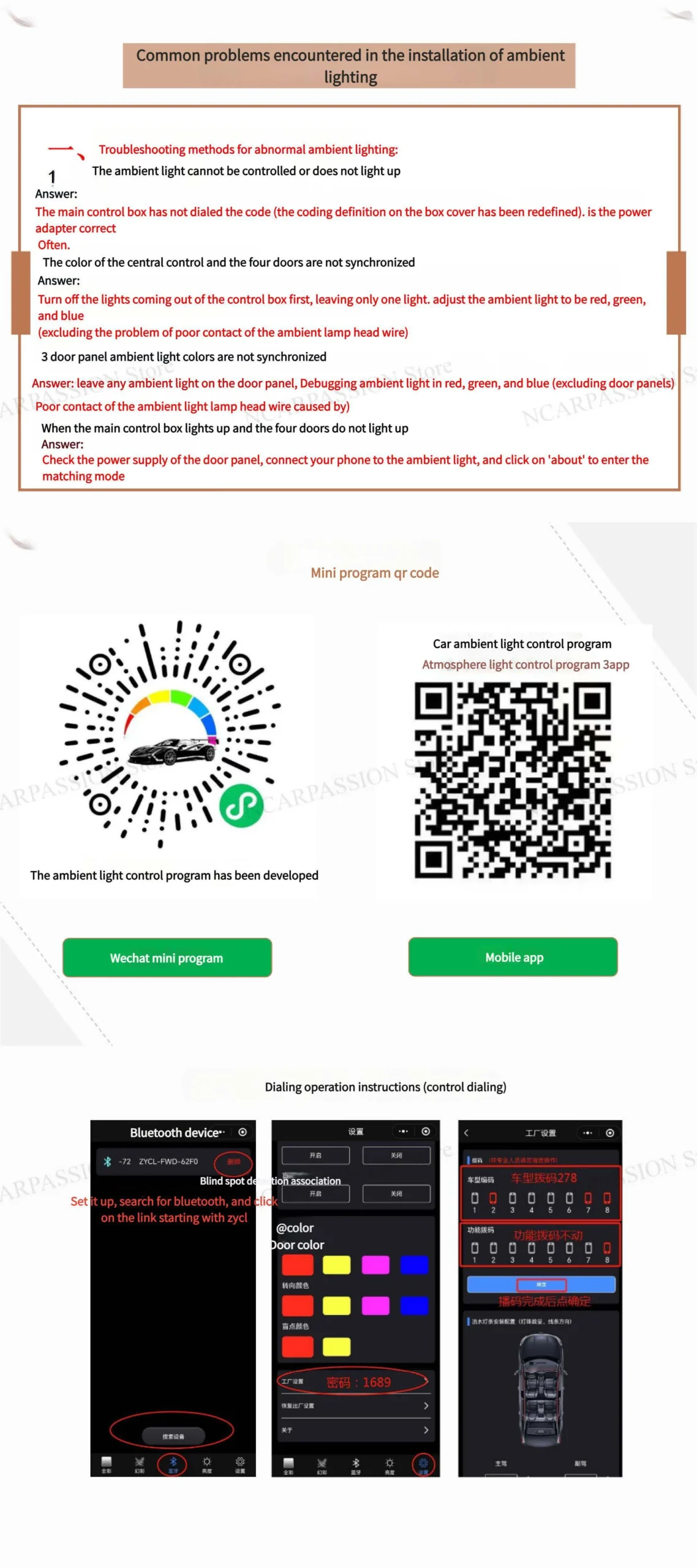
Confirm each door is wired correctly and that all connectors/colors match before connecting to the central harness. - Screen control / dial coding (computer programming required).
Use the programming cable and software to map controller channels to each door output and assign control behaviors (modes, colors, brightness). - CD-panel digital button controls & shortcuts.
Short press the CD combination button to access adjustment mode. Use these shortcuts:
1 + 4 — Mode change • 1 + 5 / 1 + 6 — Color change • 1 + 7 — Brightness adjustment - Final test, tidy and reassemble.
Power up and test each door individually and all together. Verify mode, color, brightness controls, and that no wires are pinched. Secure harnesses with zip ties and reinstall door panels.
Installation Diagrams / Images
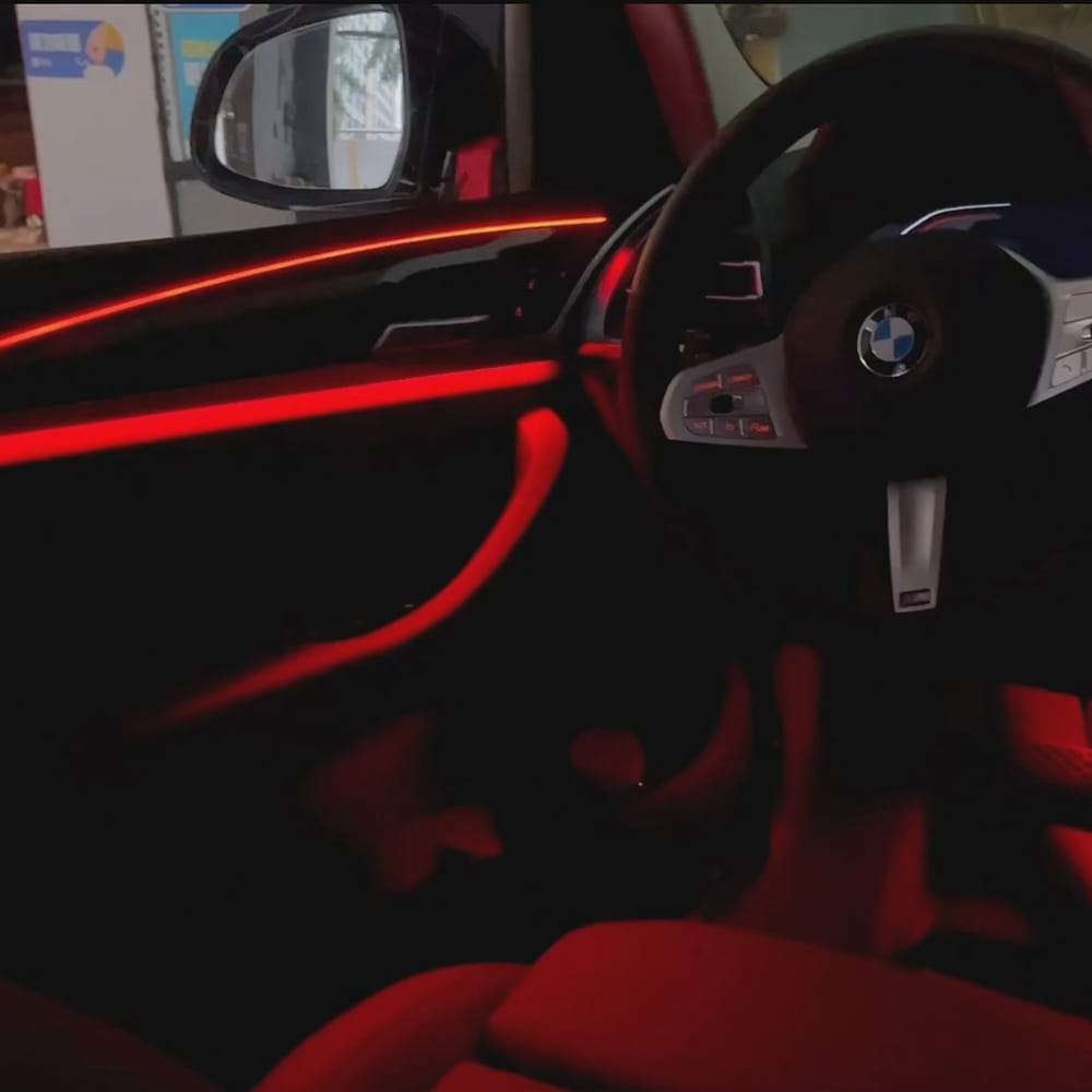
Replace the placeholders with your actual diagrams or photos. Recommended images: wiring harness close-up, solder-joint close-up, door-panel routing, final lit interior photo.
images/wiring-diagram.jpgimages/lightstrip-under-door.jpgPro Tips & Important Notes
• Leave adequate slack at hinge points; wires that are too tight will break over time.
• Use strain relief (zip ties + adhesive mounts) to prevent movement-related failures.
• If you’re not comfortable programming the controller, consult an experienced coder or certified technician.
• "PASSION Store NC" — if this is your shop profile or preset, ensure the correct profile is loaded during programming.
Troubleshooting
Door lamp does not light
Controller not responding
Intermittent flicker when door opens/closes
FAQ
- Do I need coding?
- Yes — to map outputs and enable CD-panel shortcuts and desired behaviors you will need to program the controller via laptop or programming tool.
- How long does installation take?
- Approximately 2–4 hours depending on experience and whether you have programming set up.
- Is soldering mandatory?
- If the kit uses soldered boards, yes — but some plug-and-play kits exist that avoid soldering. Always ensure secure, insulated connections.
Downloads & Resources
Replace the links below with your actual resources (wiring PDF, programming guide, product page).
downloads/wiring-diagram.pdf • Controller programming guide: downloads/controller-programming.pdf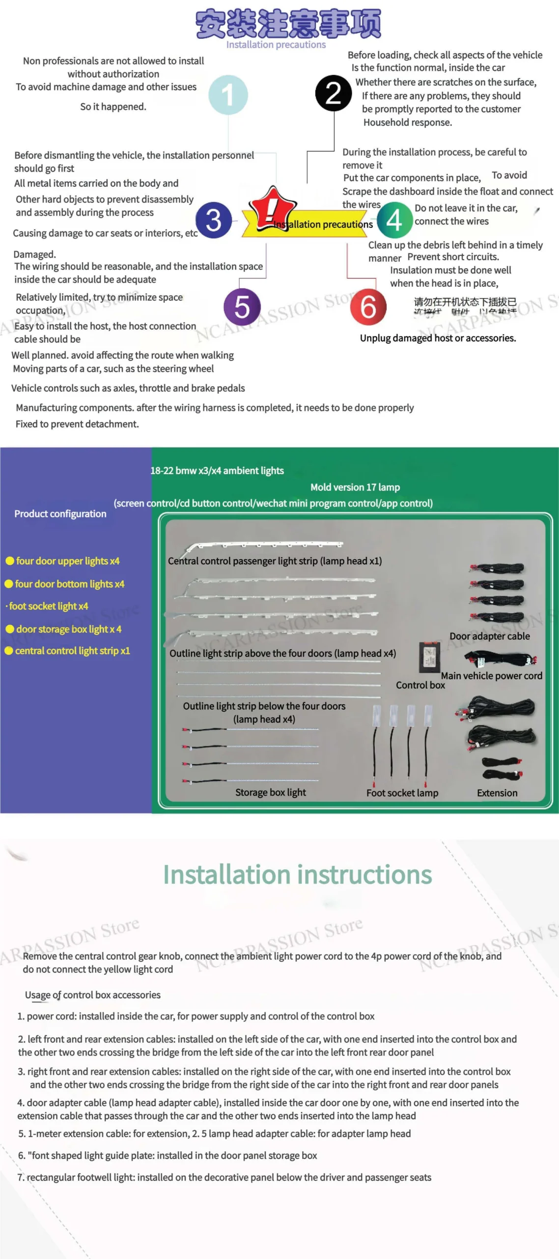

Keywords
bmw x3 g01 install | bmw x3 g01 dimensions | bmw x3 g01 body kit | bmw x3 g01 lci | bmw x3 g01 accessories | bmw x3 g01 m40i | bmw x3 g01 facelift | bmw x3 g01 2018 | bmw x3 g01 2021 | abmessungen bmw x3 g01 | bmw X3 G01 | bmw x3 g01 reliability | bmw x3 g01 facelift difference|bmw x4 g02 body kit | bmw x4 g02 lci install| bmw x4 g02 dimensions | bmw x4 g02 interior | bmw x4 g02 fuse box location | bmw x4 g02 facelift | bmw x4 g02 2019 | bmw x4 g02 m40i | spoiler bmw x4 g02 | jante bmw x4 g02 |barre de toit bmw x4 g02